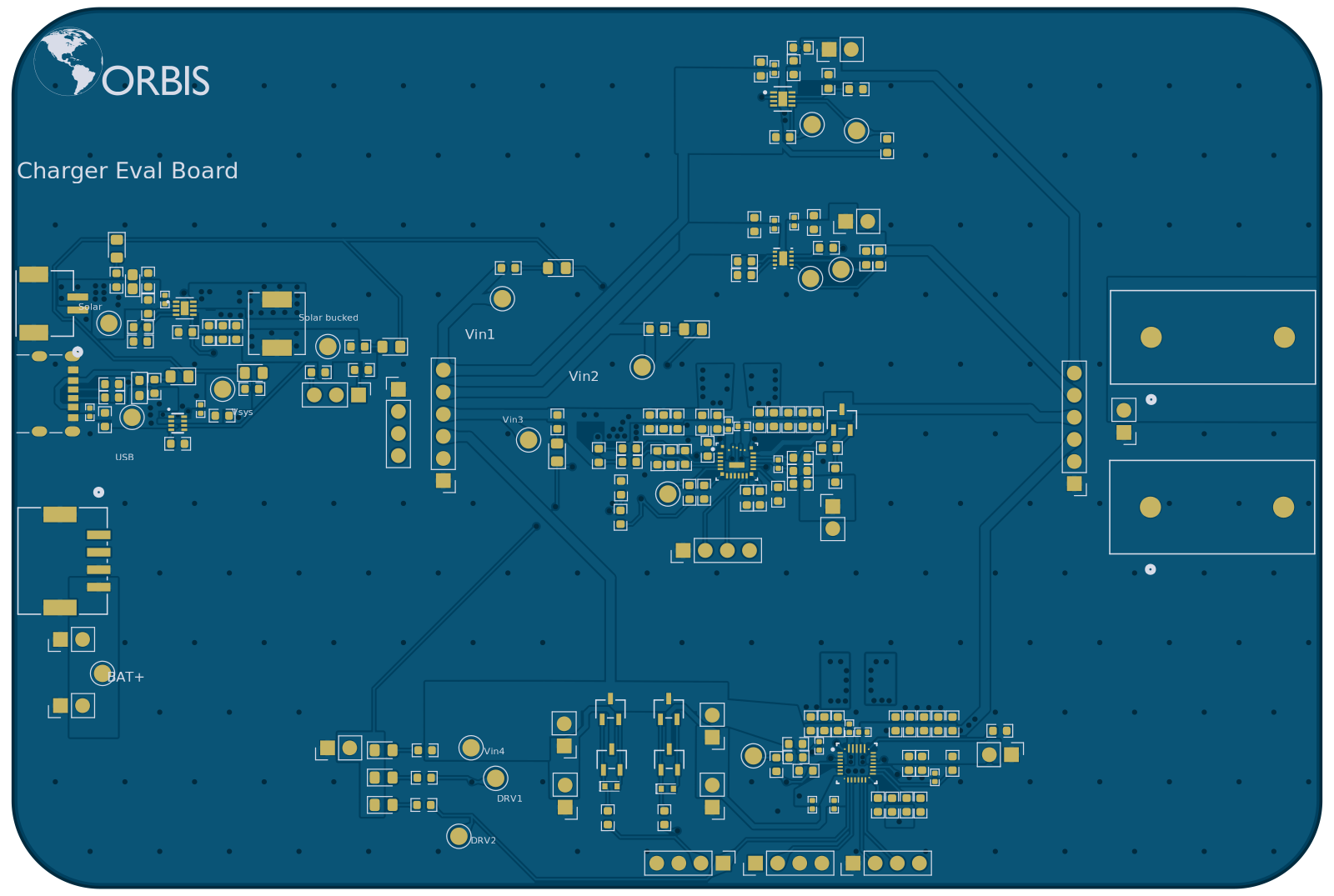
Charger evaluation board
A test fixture for choosing the battery in the flood gauge. Solar, USB, and a bench supply come in at the left. The solar leg drops through a TPS62125 buck, then an LM66200 dual ideal diode passes whichever input is highest and calls it Vsys. Jumpers route Vsys to one of four charger ICs, and whichever one is jumpered in charges the cell. The cell breaks out to an electronic load, so the same cell can be charged and discharged at temperature to compare LTO against LFP.
Input sources
Charger slot
Cell under test
The diode-OR passes whichever input sits highest, so the bench supply overrides solar the moment you enable it. Headroom is what separates the slots: the linear parts need Vsys above the cell target plus their dropout, while the buck-boost parts keep charging off a sagging panel. Pull more from the e-load than the charger can source and the cell drains no matter what the input is doing.